
On a chain conveyor with cleats, the cleats are the machine. Steel cross angles bolted between two strands of chain do the carrying, the pushing, and the metering, and they drag material along a solid steel bed. There is no belt anywhere in the load path, so there is nothing to puncture, cut, or bend.
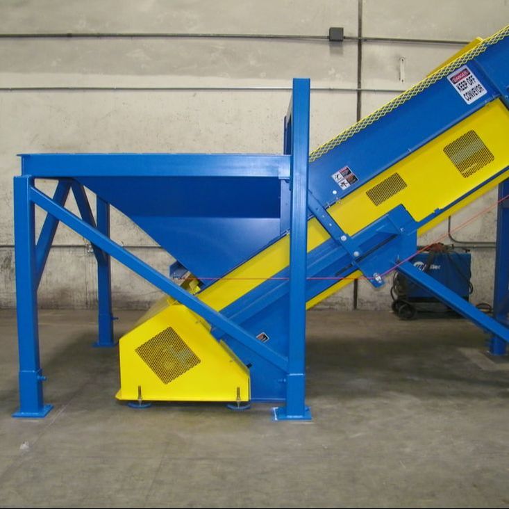
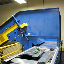
Remcon builds this style for the two jobs it is best at: pulling material out from under a hopper at a rate somebody can control, and moving metal. Both come down to the same thing. The flights are steel, the bed is steel, and every part that wears is a bolt-out item.
Steel Flights Are Cleats, Built Out of Structure
On a rubber belt a cleat is a rib molded or vulcanized onto the carrying surface. It rides on top of the belt, and its job is to keep material from rolling back down an incline. On a beltless drag chain conveyor the cleat is the carrying surface. Each flight is a length of angle iron, 3 x 3 x 1/4" as standard, bolted at both ends into the chain strands, and it takes the whole load. Nothing is glued, molded, or bonded to anything. If a flight gets bent by a loader bucket or a length of rebar, it unbolts and a new one goes on.
That changes what a cleat is allowed to do. A rubber cleat is limited by what the belt behind it can carry and by how the cleat is attached. A steel flight is limited by the steel. It can be built taller to take a deeper bite, spaced closer to hand off a steadier stream, or spaced wider to let material tumble and spread out between flights. Height, spacing, and profile are set to your material when the conveyor is drawn, and other shapes are available where an angle is not the right one. If the run has to climb, see the conveyor incline angle guide for how steep is realistic with your material.
Metering Material Out of a Hopper
This is the job the beltless build does better than anything else in the family. Put the conveyor under a hopper or a storage bunker and the flights, not the operator, decide how much material leaves. Each flight sweeps a fixed slice of the bed as it passes the opening, so what discharges is a product of flight height, flight spacing, and chain speed. A loader can dump in big, irregular loads and the conveyor still hands the next machine an even stream.
The frame can help. A dual-angle incline is the same idea built into the steel: steep where material is picked up, so the flights only take what they can hold, then shallower above it so nothing rolls back down the run. Where the rate needs to change from the control panel or from shift to shift, a variable frequency drive on the motor does it. That is why these conveyors sit under bunkers and at the head of a line as infeed conveyors, baler feed conveyors keeping a chamber filled without choking it, and sort line feed conveyors spreading material thin enough for people to work it.
Flight Size, Spacing, and the Metering Gate
3 x 3 x 1/4" angle is the standard flight, and the range built around it is wider than that suggests. Remcon drawings carry L3x3x1/4 and L4x3x1/4 angle, plain 1/4" plate cleats where an angle is not wanted, 1/4" x 4" x 4" coped angle cleats on 36" centres, and, at the heavy end, L5x3x1/4 cut 32" long and set every 24" along the chain belt. Profile, height, and spacing are three separate decisions and they get made against the material.
Which way the flight faces is a decision as well. On angle cleats the heels face forward, toward the head. That puts the flat of the leg against the material and the fold of the angle leading, so the flight takes its bite cleanly instead of scooping under the load.
The holes where a cleat bolts to its backing bar are 1/2" diameter for 3/8" bolts. That clearance is deliberate and the drawing says why: easier alignment. A row of flights across a belt has to end up straight, and building in a little float at every bolt is how that happens without a fitter fighting the steel.
Some of the holes are for a flight that may never be fitted. Every cleat on certain builds carries a pair of 7/16" holes for a possible cleat extension, to be added to every fourth cleat later if the material turns out to bridge above the belt. Punching the holes while the cleat is still flat on the table takes one extra operation, and it converts a future problem from a fabrication job into a bolt-on.
One rule on these frames is a safety rule and it is absolute: cross braces sit at least 4" clear of the cleats, to prevent a pinch point. A flight passing close to a fixed member is a shear, and the clearance is designed in rather than guarded after the fact.
Plastic appears on the flights themselves on some builds. Bolt-on 1" x 2" UHMW cleat liners take the wear against the conveyor bottom and sides and cut the friction, with the side tracks lined in bolt-on 1/2" UHMW to match. The steel flight still takes the load; the plastic takes the rubbing, and unbolts.
Where the conveyor meters out from under a hopper, a metering gate sets the depth of the layer the flights carry away. The adjustment on our existing design starts about 13/16" above the chain and opens up from there, with the upper limit set per machine. Closer is not automatically better: a gate set too near the chain raises the risk of a jam, and that trade is made deliberately when the conveyor is drawn.
The Bed Is the Wear Part, on Purpose
The solid bed the flights drag across is built in replaceable sections, sized so they are easy to handle. Standard construction is 1/4" steel plate. Hardened plate or UHMW-covered steel are available where the material is especially abrasive. The bed is meant to wear. It is the easiest part of the machine to inspect and one of the easiest to change, and it is deliberately the thing that gives up first.
That is a different failure story from a belt. A belt fails by event. Something sharp lands on it and there is a cut or a hole, and the hole grows on every pass. A steel bed fails by attrition. It thins, fairly evenly. You can see it coming, measure it, and put the swap into a shutdown you were taking anyway. And because the flights ride on the bed, they sweep it as they go, so it is harder for material to pack down into a layer somebody has to chip out.
AR400 Liners, and Welds Meant to Be Cut Out
Where the material is abrasive enough to justify it, the wear liners in the bed are cut from AR400 abrasion-resistant plate. Ours are 3/8" thick, cut either by laser or by plasma, and where a piece runs longer than 20 feet it is supplied in two lengths and spliced to final length in our shop rather than shipped as one unwieldy strip.
The more interesting decision is not the material. It is how the liner is attached.
A wear liner that is seam welded all the way round is a wear liner that has to be ground out with an angle grinder in a pit, by somebody lying down, in the dark, during a shutdown. So Remcon liners are stitch welded rather than seam welded, and the stitch pattern is laid out around the day they come off. On one liner the drawing leaves a 1/8" gap to the side plate for the explicit reason that the gap will let the welds be cut out later when the liner is replaced. On another, the instruction is two 2" welds across the top of the plate, started 3" in from the sides, so that they can be reached with a disc cutter when the time comes. That is a weld pattern designed backwards from its own removal.
The second thing done to a fitted liner is bevelling, and it exists because chain wanders. After the wear liners are welded in, a bevel is ground on the leading and following ends of each liner anywhere the chain could stray over and strike it. The same bevel goes on the inside edges of cut-outs in the tail boot sides, anywhere the chain could wander over and catch. Hold-down side flanges get a bevel a quarter inch deep on the leading edge for the same reason. None of that shows in a photograph and all of it is the difference between a chain that rides over an edge and a chain that hooks it.
Put together, it is a consistent position about wear parts. Choose the material for the duty, then attach it in the way that makes the next replacement a scheduled job rather than an excavation.
No Belt to Puncture, Which Is Why It Conveys Metal
Metal is what ends belts. Shredded scrap, punch press offal, turnings, banding, rebar ends, and the occasional unidentified steel object all arrive with an edge, and on a belt conveyor every one of them is a possible cut. Here they land on plate steel and get pushed by angle iron. There is no carrying surface to protect, so the material can be as sharp and as heavy-handed as it comes.
Heat is a separate question and this is not the answer to it. The chain slides on UHMW-faced tracks and runs under UHMW hold-down guides, and plastic has a service temperature that steel does not. For material that arrives hot, the heat-resistant carrying surface in this family is the steel pan belt on roller chain.
If your material is mixed recyclables that a continuous surface would hold better, the sibling build runs on the same frame, tracks, take-ups, and drive: drag chain with rubber or PVC belt. The choice is only about what the chain pulls. The two are set side by side on the drag chain conveyors page.
Beltless Drag Chain Specifications
Standard construction is below. Most of it is adjustable to the job.
| Item | Remcon standard |
|---|---|
| Carrying surface | None. Steel cross angles (flights) bolted between two strands of chain drag material along the bed |
| Flights / cleats | 3 x 3 x 1/4" angle iron standard; other profiles, heights, and spacings available |
| Conveyor bed | Replaceable sections of 1/4" steel plate; hardened plate or UHMW-covered steel optional |
| Chain | 4" pitch or larger, welded; options depend on the material and the load on the belt |
| Belt width | 24" to 72" |
| Best duty | Metering out of a hopper or bunker; conveying metal and other belt-damaging material |
| Installation | In-ground (in a pit) or above ground, in any of the orientations shown above |
The Chain, and What Gets Welded to It
The chain under a beltless drag is welded steel mill chain, 4" pitch or larger, specified per job. Remcon buys Webster Industries chain, and the designations that recur across the chain belt family are set out on the chain conveyors hub. They are standard numbers under ASME B29.200, not part numbers of ours.
What is particular to this machine is what gets attached to the strand, and how. The flights bolt to backing bars, and those bars are carried on tabs welded to the chain sidebars. Welding to chain is not ordinary fabrication: the sidebar is a load-carrying member on a part that articulates at every sprocket, every pass, for the life of the machine, and a bad weld on it does not fail politely.
Remcon's practice is written on the drawings. Tabs are centred on the chain sidebars and clamped before welding so they do not warp as they cool. They are welded top and bottom only, with the welds stopped short of the edges of the tab rather than wrapped around the ends. The transfer process is spray arc. Where the chain is heat treated, the tabs are preheated first; on mild steel attachments they are not, and the drawing note says so explicitly rather than leaving it to judgement. The end of a back bar is bevelled on its underside so it welds better to the chain sidebar, and a purpose-made puller holds the strand tight while the welding is done.
None of that conflicts with the chain manufacturer's own published guidance, which is worth reading if you weld to chain in your own shop. Webster's public catalog calls for an E7018 low-hydrogen electrode on mild steel attachments, no welding at all when the part is below 70 degrees Fahrenheit, preheat in the 100 to 300 degree range where it is called for, a convex rather than concave bead, and never striking an arc on the sidebar itself, because an arc scar on a sidebar can produce early chain failure.
One more part belongs to the chain rather than the frame. On some builds a sacrificial chain side wear bar is welded to the outside sidebar of the strand and centred both ways, in 1" flat bar 1/2" or 3/4" thick depending on the job, welded along the top and bottom of the bar and not across its ends. It is there so the bar rubs and the chain sidebar does not.
Built to the Material
Every one of these is drawn for the job it is going into: the flight profile, the bed, the width, the angle, and the speed. Tell us what is being fed in, what is taking it away, and whether it runs in a pit or on legs, and we will spec it and quote it from the shop floor.
Get a quote for a beltless drag chain conveyor →Frequently Asked Questions
Is a chain conveyor with cleats the same as a drag chain conveyor with steel flights?
Yes. On this machine they are the same part under two names, and Remcon's own specification for it calls them cleats. The cleat here is a length of steel angle bolted between the two chain strands, so it is structural rather than a rib molded onto a belt surface. It carries the material, pushes it along the bed, and meters it out from under a hopper. Standard is 3 x 3 x 1/4-inch angle iron, and other profiles, heights, and spacings are available.
How does a beltless drag chain conveyor meter material out of a hopper?
Each flight sweeps a fixed slice of the bed as it passes the hopper opening, so the discharge rate is set by flight height, flight spacing, and chain speed rather than by how much a loader just dumped in. A dual-angle incline helps: steep at the pickup so the flights only take what they can hold, shallower above it so nothing rolls back. A variable frequency drive lets the rate be trimmed from the panel.
What is the conveyor bed made of, and can it be replaced?
On a beltless drag chain conveyor the bed is 1/4-inch steel plate as standard, built in replaceable sections sized to be handled. Hardened plate or UHMW-covered steel are available for more abrasive material. The bed is a wear item by design. It thins gradually instead of tearing, so it can be measured and changed on a planned shutdown.
Can this conveyor handle metal and scrap?
That is what the beltless drag chain conveyor is built for. With no belt in the load path there is nothing for sharp or heavy material to cut, puncture, or bend. Shredded scrap, punch press offal, turnings, banding, and rebar ends land on plate steel and get pushed by angle iron. For mixed recyclables that need a continuous surface, the rubber or PVC belt build is the better choice.
What are the steel flights made of, and what sizes are available?
Structural angle and plate. 3 x 3 x 1/4" angle is the standard flight; the range built also includes L4x3x1/4 angle, 1/4" plate cleats, 1/4" x 4" x 4" coped angle cleats on 36" centres, and L5x3x1/4 cut 32" long on 24" spacing at the heavy end. Height, spacing, and profile are set to the material when the conveyor is drawn. Angle cleats are fitted heels forward, toward the head, and bolt to their backing bars through 1/2" holes that are oversize on purpose so a row of flights can be aligned straight.
Can the steel bed be lined with abrasion-resistant plate?
Yes. Where the material justifies it the wear liners are cut from 3/8" AR400 abrasion-resistant plate, laser or plasma cut, and spliced to final length in our shop on long runs. They are stitch welded rather than seam welded, with the stitch pattern and the gap to the side plate laid out so the welds can be cut out with a disc cutter when the liner is replaced. Leading and trailing ends are bevelled after fitting so a chain that wanders rides over the edge instead of catching it.