
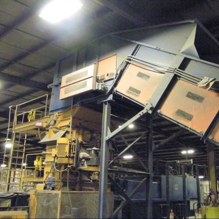
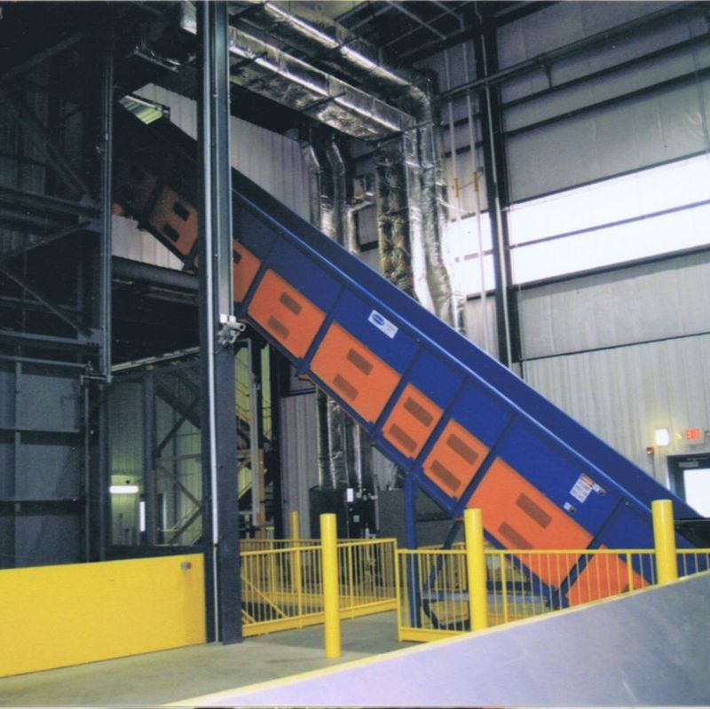
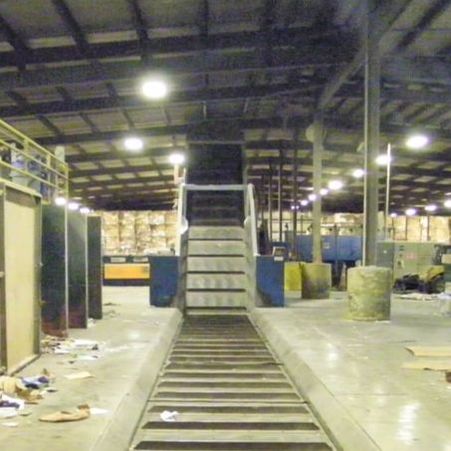
What is a roller chain belt conveyor? This is one of the most common types of chain belt conveyors used for recycling and heavy-duty material handling. The chain has steel rollers built into each link which roll on rail tracks. This reduces the drag of the belt as it travels along the conveyor and allows the conveyor to convey a heavy load with less power.
The chain belt is guided around both ends of the conveyor on sprockets. The sprockets at the discharge end of the conveyor grab the chain as the shaft and sprockets are turned by a motor with a reducer.
Multiple Belt Options
- Combo belt — rubber or PVC belting is bolted to steel cross members which connect each strand of chain, for a lightweight but durable carrying surface.
- Steel belt — steel pans are bolted to tabs or cross members attached to each strand of chain, for a heavy-duty and heat-resistant carrying surface.
The Belt and the Machine, From One Shop
Anyone shopping for a chain conveyor belt is usually in one of two situations, and the industry tends to make you pick a vendor by which one you are in. Either you need a conveyor built and the belt comes with it, or you already have the conveyor, often somebody else's, and the belt on it is finished. Belt houses are set up for the second. Machine builders are set up for the first, and usually send you elsewhere for the second.
Remcon does both, because a chain belt is something we build rather than order in whole. A combination belt is an assembly: two strands of chain, steel cross members, rubber or PVC belting or die-formed steel pans bolted down on top, plus cleats, side wings, and impact shoes. We build that assembly to the conveyor it is going on, matched to the sprockets already turning on the head shaft, the rail or track already in the frame, and the take-up travel available to install it with. It does not have to be a Remcon conveyor. Most brands and styles can be matched.
Individual parts come the same way. Cross members, cleats, wear strips, impact shoes, chain, and tracks are all separate items, so a belt that took local damage gets a local repair instead of a full change-out. When the whole belt does come off, our own crews do the change on site during a planned shutdown.
See replacement conveyor belts for measuring and lead times, or belt replacement and repair for on-site service.
Common Roller Chain Conveyor Uses
Roller chain belts carry the hardest-working conveyors in a recycling plant. Each use has its own entry:
Conveyor Orientation Options
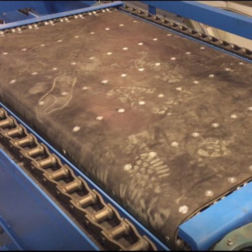
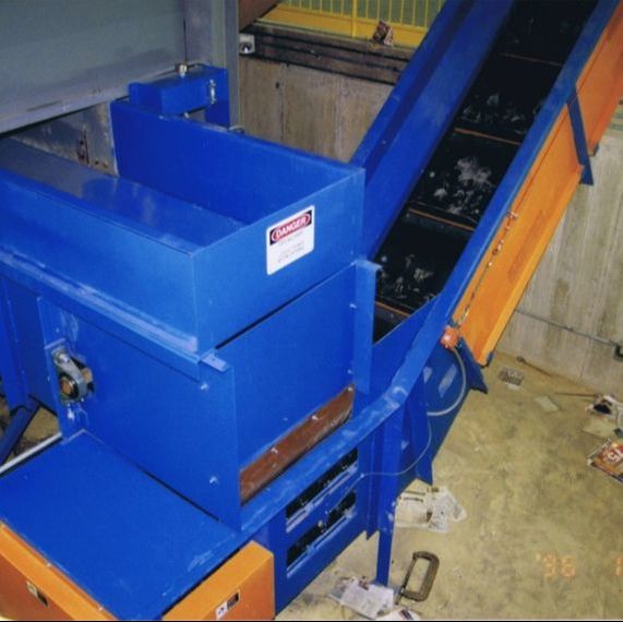
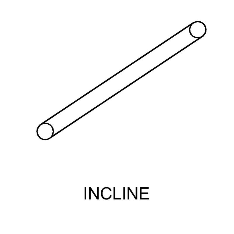
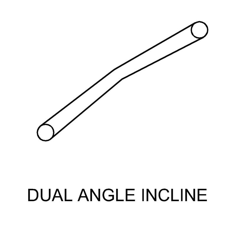
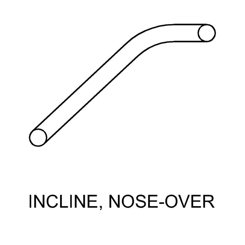
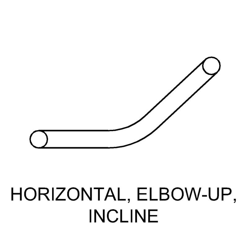
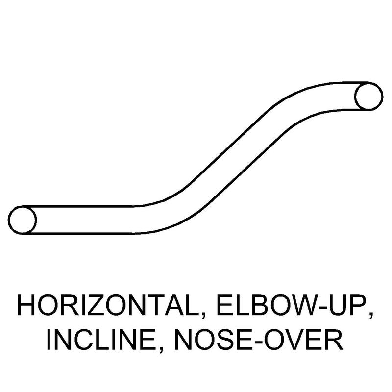
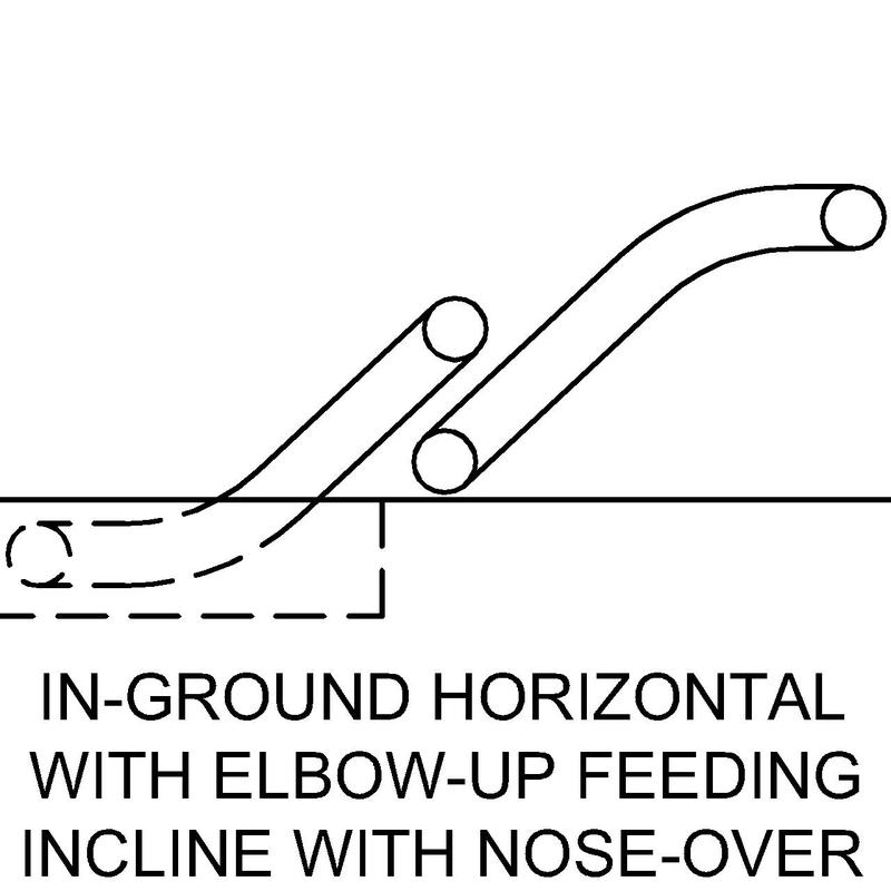
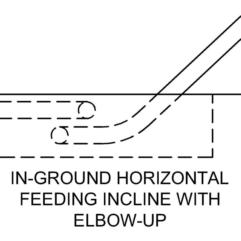
Remcon can build roller chain conveyors in many different orientations, depending on the layout requirements. We also can build two separate conveyors that run in series, to simplify installation, separate clumps better, or to be able to use two different types of conveyors (e.g. a roller chain feeding a slider bed). Other options may be available, depending on the application.
All of these orientation options can be installed both in-ground (in a pit) or above ground.
Contact us to discuss what layout works best for your situation →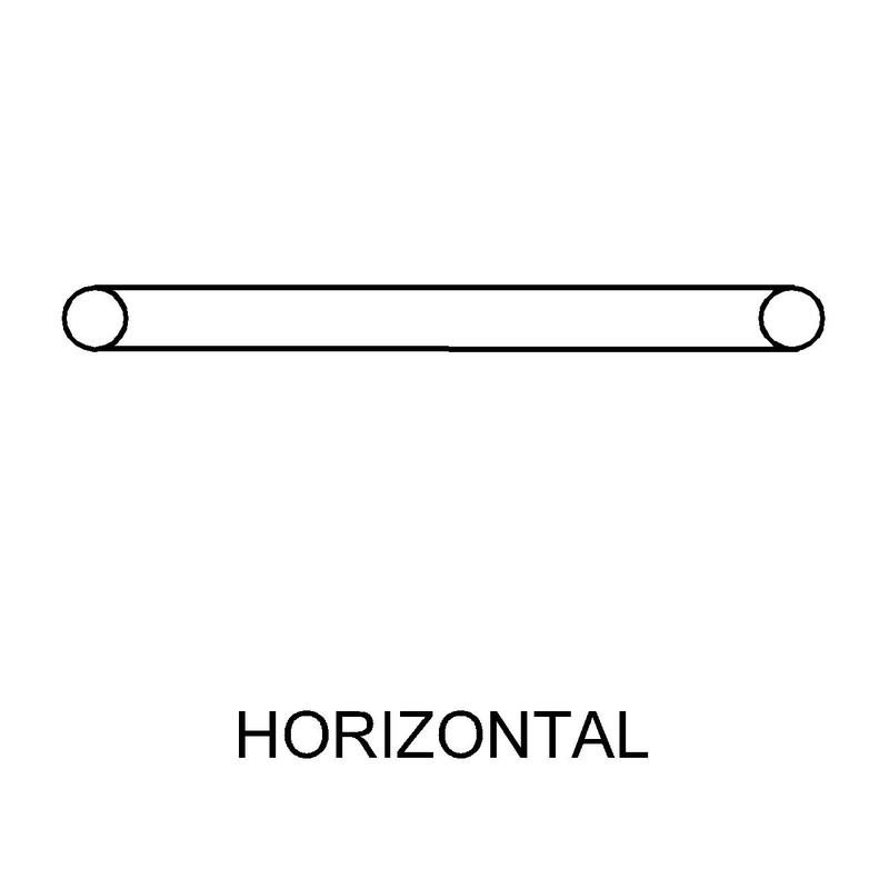
Special Features & Specifications
The sections below cover the standard construction of a Remcon roller chain conveyor, from the frame up. Ask us for the Roller Chain Conveyor General Features Drawing (PDF) when you get in touch.
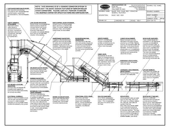
Roller Chain Conveyor Specifications at a Glance
The table below summarizes the standard construction; the sections that follow explain each item in detail.
| Specification | Remcon standard |
|---|---|
| Frame | Heavy-duty open structural steel with formed plate at elbows — completely shop fitted and welded |
| Section length | Shop fabricated in the longest sections practical, up to 40 ft.; aligned in the shop, re-aligned and leveled at installation |
| Belting | Rubber/PVC combo belt or steel pan belt, widths 24" to 72" |
| Chain pitch | 6" or 9" |
| Chain rollers | Single flange, 3" diameter x 1 1/2" width, sintered steel |
| Rails | 30 lb. ASCE rail — replaceable, not used as part of the conveyor frame |
| Impact beams | Custom channels formed from 1/4" plate with 3" flanges and a 6" web; 1/2" x 6" UHMW wear strips |
| Sprockets | 6 tooth with hardened teeth — 12" pitch diameter (6" pitch chain) or 18" pitch diameter (9" pitch chain) |
| Drive | Shaft-mounted Dodge Torque Arm II reducer, v-belt driven; VFD (variable frequency drive) recommended |
| Belt take-up | Cantilevered telescoping tube style — 12" travel on shorter conveyors, up to 18" on the longest |
| Backstops | Constantly-engaged running backstops, plus maintenance backstops for belt work |
| Emergency stop | Cable-pull switch with required cable and rigging |
| Installation | In-ground (pit) or above ground; shipped and installed nationwide from Airway Heights, WA |
Specifying the Chain and the Sprockets
Engineering-class roller chain is identified by four numbers, and a conveyor cannot be quoted against an existing machine without them: pitch, roller diameter, roller width, and the section of the sidebar. Remcon's standard build is 6" or 9" pitch running 3" diameter by 1 1/2" wide single-flange rollers, which is what the specification table above is describing.
Our own chain runs double-row sidebars 2" wide by 3/8" thick in die-punched 1045 bar, on 3/4" headed stub pins, which is the set in the table. Somebody else's conveyor will have its own, and the only way to know it is to measure it. One machine we matched carried 3" single-flange rollers on 3/8" x 2" sidebars at 6" pitch, which happens to land in the same place; the next one need not. Those four numbers are the ones we ask for first when somebody calls about a replacement chain belt, because until they are measured there is nothing to build against.
The sprockets get specified in the same detail, because they are half of the wear pair. A head drive pair on 6" pitch chain with 3" rollers is written up as six-tooth split drive sprockets, bored and keyed with two set screws, teeth flame hardened, and keyed in time. The tail sprocket is not split: it is either keyed the same way or bronze bushed with greaseways and a grease zerk, and the drawing note says it must slide onto the shaft by hand.
The reason the head is split and the tail is not is written on the drawing too. Split sprockets get set screws on both sides because a split sprocket needs the extra support, and the second set screw also makes it impossible to fit one backwards. The tail is left solid because tail shafts are easy to change anyway, and because a pit conveyor's shaft comes out rusty enough that nobody wants to re-use it.
Timing is checked before the sprockets leave the bench. Both head sprockets go onto one short test piece of keyed shaft at the same time, and each pair of teeth is checked against a combination square laid on the table. The faces of the teeth that actually contact the chain are the critical ones, so they are marked, which also fixes the direction of travel. Two sprockets a tooth out of time on the same shaft will pull one strand of chain ahead of the other for the life of the machine.
Conveyor Features
Structural Steel Conveyor Frame
Heavy-duty open frame construction from structural shapes and formed plate at elbows, braced and reinforced for rigidity in all places and completely shop fitted and welded. The frame is specially designed to allow more access between upper and lower belts and includes special expanded maintenance openings.
Conveyor Alignment
Remcon conveyors are shop fabricated in the longest sections practical (up to 40 ft.). Adjoining sections are aligned accurately with each other in the shop as they are fabricated. The entire conveyor is aligned (and leveled) a second time during the installation, to prevent the belt from wandering and wearing into the side of the conveyor.
Leg Height and Leveling Adjusters
Conveyor legs are equipped with threaded height adjusters for fine-tuning the height and for leveling the conveyor accurately.
Oversized, High-Strength Impact Beams
Remcon impact beams are parallel to the belt, custom fabricated channels, formed from 1/4" plate, with 3" flanges and a 6" web. This design provides a shape that is stronger and is made from a material that has a higher yield strength and is straighter than structural channel. These high-strength beams have additional support in the loading area, where there is more potential for abuse.
UHMW Plastic Wear Surfaces on Impact Beams
1/2" thick x 6" wide black reprocessed UHMW polyethylene plastic is attached to the conveyor impact beams. (Reprocessed UHMW is used due to the improved wear properties achieved by the cross-linking that happens during the production process.) When sufficient load is applied to the belt to cause the impact channels to flex, the impact shoes will ride on the UHMW wear strips rather than directly on the steel impact beams. The plastic is attached with bolts, is easily replaced, and has slotted holes that allow for thermal expansion to prevent buckling in warm weather.
Roller Chain Rails
30 lb. ASCE rail designed to provide tracking for the rollers. This is a replaceable item and is not used as part of the conveyor frame.
Running Backstops
Constantly-engaged running backstops allow the return belt to pass through while the belt runs forward, but prevent roller chain belts from back-running while the conveyor is stopped during normal operation.
Wear-Reducing Rail Transitions
The head end of Remcon's roller chain tracks are specially shaped and positioned to minimize damage to chain and tracks from the up-and-down chordal action of the chain going around the head sprockets.
Remcon Belt Take-Ups
Remcon's cantilevered telescoping tube style take-ups, with manual screw adjustment, offer the following advantages:
- Cleaning access — the support tubes are positioned to provide access to the area between the upper and lower belts, for cleaning and inspection of the tail pulley on slider bed conveyors, or the tail sprockets and shaft of chain/belt conveyors.
- Replaceable parts — the bearings are commonly available pillow block style. The threaded working parts of the take-up are commonly available from local fastener or hardware stores, and are replaced easily.
- Take-up travel — generous length of take-up travel: 12" on the shorter conveyors and up to 18" on the longest. On slider bed conveyors, the belt will be cut so that the majority of the take-up is used for ease of belt installation, repair and replacement, since good quality belts with polyester carcasses have virtually no stretch after initial tensioning, and in some cases will shrink slightly.
- Ease of adjustment — tracking and tension adjustments are made with one wrench, with no need to loosen and re-tighten the bearing attachment bolts. The moving parts of the take-up have generous amounts of clearance, to prevent binding in the frame or against the bearings (side load) as the take-up moves through its full range.
- Versatility — Remcon take-ups will accommodate almost any brand of bearing, in the most common, pillow block style.
Tracking Adjustments on Both Ends of Conveyor
Additional belt tracking adjustments are provided for the non-take-up end of each conveyor, for ease of tracking adjustments.
Drive Method — Parallel Gear, Shaft-Mounted Torque Arm Reducers (Dodge Torque Arm II)
These reducers have been used almost exclusively in sand, rock, gravel, mining, and similar industries for many years, and are well proven. Remcon has used them since 1990, with good success. The new generation has been re-engineered throughout with features designed to improve performance, extend service life, and reduce maintenance. Remcon normally configures these reducers to be driven by a separate motor by v-belts, using different combinations of sheaves for additional speed reduction.
The advantages of using the Dodge Torque Arm II shaft mount reducer with v-belt drive are as follows:
- Low maintenance — there are no chains to oil, tension, or shorten and reconnect.
- Ease of adjustment — rather than moving the entire gearbox and motor to adjust the chain tension, adjusting the Dodge Torque Arm II reducer only requires opening the hinged door on the belt guard, loosening the two lock nuts, and turning the turnbuckle by hand.
- Fewer wear parts — there are no sprockets or chain to wear out. Although v-belts will wear out, they commonly do not wear out until they are protecting the conveyor from jamming, if it jams (see following item). They are inexpensive and easy to replace. V-belt sheaves last much longer than drive chain sprockets and drive chain.
- Jamming protection — the need for mechanical shear pins is eliminated. The motor drives the reducer by v-belt(s). If the conveyor jams, the v-belt slips, preventing the jam from causing damage to the conveyor. As the v-belt is slipping, it typically makes a loud squealing noise that draws attention to the problem. If the conveyor is not turned off, the v-belt will eventually be ruined, and there will be nothing driving the jammed conveyor. The v-belt is the cheapest part in the drive to replace. Replacing the belt involves opening the hinged belt guard door, loosening the turnbuckle and slipping the new belt on. If the conveyor is prone to jamming (for example wrong product, or too much product), the v-belt can be kept looser than normal to minimize the potential for damage. We are unaware of any Remcon conveyor equipped with these reducers that suffered damage resulting from jamming. As additional jamming protection an electronic shear pin may be added to the electrical system.
- Parallel gears — the gears are parallel, rather than right angle. Parallel gears are more efficient and produce less friction.
- Operating and maintenance convenience — when working on a conveyor, such as doing maintenance, un-jamming product or diagnosing problems, there is often a need to move the belt a short distance either forward or backward. This is impossible electrically, since the power should be locked out at this time. But this can be accomplished easily and safely without power when using a shaft-mounted reducer, by turning the spokes on the input sheave by hand.
- Excellent availability — unlike other reducers, the Dodge Torque Arm II reducers are so commonly used in other industries that they are quite often in stock at many local dealers, and are almost always available somewhere in the country. Other brands (Link, Browning, etc.) may also be substituted without modification.
- Separate motor — the motor is mounted separately from the reducer, and is connected only by v-belts. Therefore, any brand of motor can be used, and a motor breakdown does not affect the reducer, or vice-versa.
- Ease of changing reduction ratios — reduction ratios of up to 5 to 1 are easily obtained from the motor-to-reducer v-belts and sheaves. These ratios are easily changed by swapping out sheaves, which is more difficult and expensive with a drive chain and sprockets.
Variable Frequency Drive (VFD)
A VFD can be a very worthwhile component to have on a conveyor, and is especially recommended on chain belt conveyors. VFDs offer:
- Soft start — decreases wear and tear on the motor and other drive parts
- Jam protection — replaces old technology (shear pins, clutches, etc.) and works better
- Many other programmable settings for speed, acceleration and deceleration, etc.
Chordal Action, and Why the Rail Transitions Are Shaped
A chain does not wrap a sprocket in a circle. It wraps it as a polygon, one flat per tooth, so the centreline of the chain rises and falls once for every tooth that goes past. That is chordal action, and the fewer the teeth the larger the rise and fall. It is the reason a chain belt has a gentle pulse in it at low speed and the reason the rollers arrive at the track at slightly different heights depending on where in the tooth cycle they leave the sprocket.
Remcon drew the problem out rather than living with it, comparing the chordal action of a six-tooth sprocket against a seven-tooth on the same chain. The layout rules that came out of that study are written on the drawings, and whether they are applied is called out per job:
- The bottom track is lined up with the highest position of the rollers coming off the sprocket, so the chain settles onto the rail instead of dropping onto it.
- The top track is spaced one pitch diameter, rounded off, from the lower track.
- On a seven-tooth sprocket the track spacing is set exactly equal to the pitch diameter, which is an awkward dimension on a seven-tooth and is the sort of thing that gets rounded away by accident.
- Through a curve, the point where the roller first strikes the track is positioned so the chain is on the upstroke of the chordal action when it makes contact.
- Where a shaft sits below the chain line, the centre is set low enough to clear the chordal radius with clearance left over between the chain and the plastic beneath it.
The wear-reducing rail transitions described above are the visible half of that work. The geometry behind them is this.
Wrap angle is the other layout rule the drawings carry. The minimum recommended angle of wrap for roller chain is 120 degrees, per the Diamond Chain and HKK Chain published guidance, and the note that records it goes on to say where it bites: when routing the return chain around a nose-over, if there is room, let the chain come off the head sprocket horizontally and curve down into the incline rather than curving up and then back down.
One more decision belongs here because it is about the same failure. Remcon fits a chain-engaging backstop rather than a gearbox backstop, and the reason is written plainly: if the conveyor jams, somebody may well be standing on the belt looking for the jam, and that is exactly the moment a drive chain or a conveyor chain can fail. A backstop that grips the conveyor chain still holds the belt when the drive train between the gearbox and the chain has let go.
Belt Specifications
Rubber/PVC Combination Belts
- Belt material — 3 ply, 330 lbs. per inch width (P.I.W.) MOR rubber, 3/16" top cover; 1/16" bottom cover
- Belt cross members — 4" x 5.4 lb. channel (6" pitch) or 6" x 8.2 lb. channel (9" pitch), bolted to chain and belt every other pitch
- Belt width — 24" to 72"
- Chain bushings — solid .760" I.D. x 1.120" O.D. x 2.31" long, 1018 solid machined; carburized, hardened to RC55-60; press fit into inner sidebars
- Chain sidebars — double row, 2" wide x 3/8" thick precision die punched 1045 bar
- Chain pins — 4142 steel 3/4" diameter headed stub pin; pin ends milled flat to lock into outer sidebars and ends drilled for 1/4" x 1" solid locking pin
- Chain pitch — available in either 6" or 9" pitch
- Cleats — 3 x 3 x 3/8 coped angle on 48" centers (other options also available)
- Impact shoes — 3" x 6" x 3/8" thick plate, welded to underside of cross channels in line with impact beams
- Rollers — single flange, 3" diameter x 1 1/2" width, through-hardened sintered steel wheel
- Side wings — 1/4" thick steel x 4" tall, precision die formed interlocking offset wing
- Sprockets — 6 tooth, 12" pitch diameter (for 6" pitch chain) or 18" pitch diameter (for 9" pitch chain), flame-cut with hardened teeth at tail and head ends of conveyor
Steel Pan Belts
Hinge pan specifications are given below — contact us for other steel belt options.
- Belt width — 24" to 72"
- Chain bushings — solid .760" I.D. x 1.120" O.D. x 2.060" long, 1018 alloy, machined, carburized, hardened to RC55-60, press fit into inner sidebars
- Chain sidebars — double row, 2" wide x 1/4" thick precision die punched 1045 alloy steel
- Chain pins — 1045 cold rolled steel, .750" diameter, pin ends milled flat to lock into outer sidebars and ends drilled for 1/4" x 1" extended prong cotter pin
- Chain pitch — available in either 6" or 9" pitch
- Chain rollers — single flange, 3" diameter x 1 1/2" width, face sintered steel
- Cleats — 3 x 3 x 3/8 coped angle iron on 48" centers (other options also available)
- Hinge pans — 1/4" steel plate, precision die-formed pan, with fully closed loops, 2 loops welded closed on each side of the belt
- Hinge sleeve — 0.975" O.D. x .760" I.D. tube, 1008/1010 hot rolled pickled and oiled steel. That is a 0.1075" wall. The sleeve is interchangeable with standard hinge sleeves and spans the entire width of the belt.
- Impact shoes — 1" plate, 3" x 6" spaced every 12", welded on underside of steel belt pans in line with impact beams
- Side wings — 1/4" thick steel x 4" tall, precision die formed, interlocking, offset wing, fully welded to hinge pan to prevent leakage of product
- Sprockets — 6 tooth, 12" pitch diameter (for 6" pitch chain) or 18" pitch diameter (for 9" pitch chain), flame cut with hardened teeth at tail and head ends of conveyor
Maintenance & Safety Features
Remcon's roller chain conveyors are designed to allow the safest and easiest access to maintenance areas to ensure a smooth running operation.
Enlarged Maintenance Access
Special open frame design maximizes access between upper and lower belts and includes special expanded maintenance openings.
Hinged Guards for Drive Components
Remcon's standard guards include a hinged door that provides convenient access for inspection and maintenance without removing a guard. For conveyors that have insufficient clearance for a hinging door at the drive, the door — rather than the entire guard — is unbolted to gain access.
Maintenance Backstops
In addition to backstops that prevent roller chain belts from back-running during normal operation, additional maintenance backstops are provided for safety and convenience during maintenance work such as belt installation.
Self-Cleaning Belt Return Chutes and Guarding
The entire underside of the conveyor, from the discharge to the floor, is guarded for safety and cleanliness. Debris that clings to the belt falls into the chutes (rather than the floor), then slides down the chutes, which are free of catch-points. It then collects in a guarded collection point at floor level (and outside of the pit, if there is one). The chutes are easily removed for maintenance.
Debris Clean-Out Door
Debris that slides down the return belt chutes is collected in this guarded area. The door provides convenient cleaning access.
Chain Oiler
Automatically oils the belt chains for increased longevity. The heavy duty steel tank has a 2.5 gallon capacity and features electric valves to start and stop the flow of oil as the conveyor starts and stops.
Emergency Stop System
Cable-pull switch with required cable and rigging.
In-Pit vs. Above-Ground Installation
Every orientation shown above can be installed either in-ground (in a pit) or above ground, and the choice usually comes down to how material reaches the conveyor. An in-pit roller chain conveyor puts the loading section below floor level, so a wheel loader or skid steer can push material straight onto the belt — which is why infeed and metering conveyors in recycling plants are so often installed in pits. The pit is covered by Remcon's deck plate system (detailed below), built to carry loader traffic, and the self-cleaning return chutes deliver debris to a guarded collection point at floor level, outside the pit.
An above-ground installation avoids the concrete work — the conveyor stands on legs with threaded height adjusters, and material arrives from another conveyor, an infeed hopper, or an elevated floor. The two approaches also combine: a common layout is an in-ground horizontal section with elbow-up feeding an above-ground incline, shown in DWG. 07 and DWG. 08 above.
Pit Deckplate Features
Remcon also manufactures deck plates and supporting framework custom designed to fit each pit conveyor. We offer a system that allows the easiest access to the inside of the pit for maintenance, while keeping the loading floor safe and secure during operation.
Deck Plates
1/2" thick plate, with 3 x 3 x 3/8" angle stiffeners, 5 feet typical length. Pit deck stops welded to the underside of the deck plates prevent the plates from being slid apart by a skid steer machine. They also act as guides to allow removal and re-installation of the plates by one person on a forklift, using the lift-out deck plate handles.
Lift-Out Deck Plate Handles
These heavy duty handles are inserted into special holes in the center of the plates. A forklift is then used to remove and re-install the plate, all by one person.
Deck Plate Supports
Steel tube, 3 x 3 x 1/4" or larger, with one end welded to the steel embedded in the top of the concrete pit wall (curbing angle) and the other end welded to the conveyor. These tubes are installed underneath the 1/8" gaps between all the deck plates, and are spaced 4 to 5 feet apart. The deck support tubes serve the following functions:
- Provide additional support for the deck plates, to bear the load of bucket loaders, etc.
- Block small debris from falling through the small gaps between plates and into the pit
- Act as strong stops to keep the removable pit plates locked into place
- Protect the conveyor from damage by bucket loaders by tying the conveyor into the concrete pit wall every 5 feet
- Provide a positive means of locking the conveyor into a very accurate alignment despite all the abuse it normally receives. A misaligned conveyor results in excessive wear to both the belt and the rails that the belt rides on.
Roller Chain Belt Conveyor FAQ
What is a roller chain belt conveyor?
A roller chain belt conveyor is a chain belt conveyor whose chain has steel rollers built into each link. The rollers roll on 30 lb. ASCE rail tracks instead of sliding, which reduces the drag of the belt and lets the conveyor move a heavy load with less power. It is one of the most common chain belts in recycling and solid waste plants.
Roller chain or slider bed — which do I need?
Choose a roller chain belt for heavy loads and the hardest-working positions in a plant — baler feed, infeed, and metering duty. A slider bed conveyor is the more affordable choice for light to medium loads. The two also work in series: a common Remcon layout is a roller chain conveyor feeding a slider bed.
What is the difference between a roller chain and a drag chain conveyor?
Both are chain belt conveyors — the difference is how the chain travels. On a drag chain conveyor, the chain lies flat and slides on UHMW wear tracks; on a roller chain conveyor, steel rollers built into each link roll on rail. Rolling drags less than sliding, so roller chain is the heavier-duty option where the load, the length, or the incline demands more from the drive.
What belting options are available on a roller chain conveyor?
Two belt styles are standard: a combo belt — rubber or PVC belting bolted to steel cross members connecting each strand of chain — or a steel pan belt with 1/4" die-formed hinge pans for heavy-duty, heat-resistant service. Both come in belt widths from 24" to 72", on 6" or 9" pitch chain.
How long are the sections and how does the conveyor ship?
Remcon shop-fabricates roller chain conveyors in the longest sections practical — up to 40 ft. — and aligns adjoining sections with each other in the shop as they are built. The conveyor ships in those sections, then the entire conveyor is aligned and leveled a second time during installation to keep the belt from wandering and wearing into the side of the conveyor.
Does Remcon install roller chain belt conveyors nationwide?
Yes. Every conveyor is designed and fabricated at our shop in Airway Heights, Washington (Spokane area), then shipped and installed nationwide with our own installation crews. We also supply replacement belts and parts for the life of the machine.
Can I order a chain conveyor belt without buying a conveyor?
Yes. Remcon fabricates combination chain belting — chain, steel cross members, rubber or PVC belting or steel pans, cleats, and side wings — as a replacement item, and most brands and styles can be matched. Send the belt width, the chain and sprockets already on the machine, and a measurement of the existing belt, and we will build it to fit. Individual parts are available on their own, and our own crews install on site. Call (509) 244-9439.
Can Remcon match the roller chain and sprockets already on my conveyor?
Usually, yes, and most brands and styles can be matched. What we need is the chain pitch, the roller diameter and width, the sidebar thickness and height, and the pin diameter, plus the tooth count and bore of the sprockets already on the shafts and the take-up travel available to install with. Our own chain runs 2" x 3/8" double-row sidebars on 3/4" pins, but a machine we did not build will have its own section and we work to what is measured rather than to a standard. Send the measurements or the old chain and we will build the replacement belt to them.
What oil goes in the chain oiler?
A lightweight gear oil, 75W or 80W. The note on our drawings makes the point that this is thinner than 30W motor oil, which is the substitution to avoid. Each oiler tank has two valves, both opening when the conveyors run and closing when they stop, with a junction box on the tank assembly. The oiler is a standard feature on roller chain builds because rolling contact still needs the pin and bushing joint lubricated, and a dry joint is what makes a chain elongate early.
We specialize in custom designed and fabricated equipment and can work with you to design a solution that will work well for your needs. Every roller chain belt conveyor is designed and fabricated at our Airway Heights (Spokane), Washington shop, then shipped and installed nationwide. Contact us to discuss options or to get a quote.
Start your roller chain conveyor quote →