
Two strands of chain do the pulling. The belt only has to carry. On a drag chain belt conveyor, heavy rubber or PVC belting bolts down onto the steel cross members that tie the two strands together, giving a continuous carrying surface with a positive drive underneath it. It is the general-purpose chain belt Remcon builds for feed-end duty in a recycling plant.
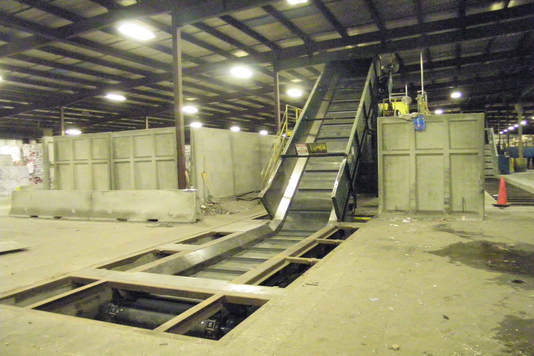
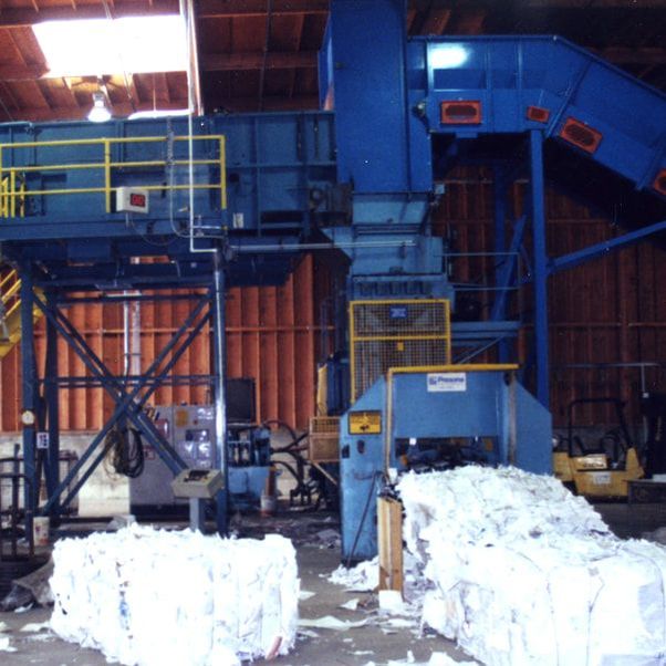

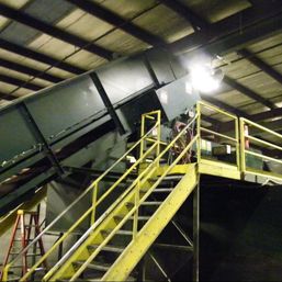
This page is about the belt: what it is made of, how it is attached, how it is repaired, and what holds it up in the loading zone. The chain, the tracks, the take-ups, and the drive are shared across the whole family and are covered on the chain conveyors hub.
The Chain Pulls, the Belt Carries
On a conventional belt conveyor the belt is a structural member. It is what transmits the drive to the load, so the carcass has to be strong enough to be pulled on for the whole length of the machine. On a chain belt that job belongs to the chain. The sprockets engage the chain, the chain takes the pull, and the belting rides along as a surface for material to sit on.
Which is why the belt spec on this machine reads the way it does. Remcon's standard is 3-ply, 330 pounds per inch of width MOR rubber, or 450 lb. PVC. Those are working tension ratings. On a friction-driven conveyor the number tells you how hard the drive is allowed to pull. Here it buys something else: a carcass heavy enough to hold bolts without tearing out at the holes, and heavy enough to take material dropped on it from a bucket without the plies letting go of each other.
Which Chain Goes Under the Belt
Welded steel mill chain, 4" pitch or larger, and it is the component the belt spec is written around. Most of our belt drawings do not bother with a designation at all: they record the maker and the pitch and leave it there, because for this family the pitch is the number that governs the belt layout above it.
Where a designation is called out it is Webster Industries chain. WR78-4 and the 124 series sit at 4.000". WH111+ runs 4.760" and appears under the wide, heavily loaded machines. Replacement belts matching an older conveyor sometimes land on a combination chain instead, cast blocks carried on steel sidebars, in which case it is usually N102B at 4.000" or N131 at 3.075". All of these are standard numbers under ASME B29.200 rather than anything proprietary, and the chain conveyors hub sets out the family with pitches.
Between the chain and the belting sit the back bars, and their dimensions are a fair summary of how this machine is built. The usual section is 3/8" x 4" flat bar; newer belts use 1/2" plate back bars laser cut to shape. Two details about how they are fitted matter more than the section does.
The first is height, and it is not the same for both. The fitting note calls for back bar tabs to be set flush with the bottom of the chain, and for belt tabs to sit 1/8" above it. Either way it is a called-out dimension rather than something judged at the bench, and the tabs are clamped before they are welded so they do not warp as they cool.
The second is what they slide on. The back bars run on UHMW slide strips, not on steel. Plastic under the bars, plastic under the chain, and steel only where steel has to be.
Rubber or PVC
MOR stands for moderate oil resistant. It names the cover compound, and it is what Remcon specifies as standard on the rubber belt. Read it as one field in the spec rather than the whole spec. How well a cover survives gouging and abrasion is set by the cover grade and the cover thickness, which are separate decisions from the oil rating and get made per job. Our guide to reading a belt spec takes the line apart field by field.
PVC is the other standard. It stretches very little, it holds mechanical fasteners and bolts well, and it is not troubled by damp. Which one belongs on your conveyor comes down to what is landing on it and what has already lasted in your plant. Tell us the material and how it is loaded and we will spec the belt. We also fabricate replacement belting for conveyors we did not build, so we get to see what survives and what does not.
Bolted, Not Spliced
A friction-driven belt is an endless loop. It has to be spliced, vulcanized or laced, and that splice is a permanent feature of the machine and a permanent thing to watch. A chain belt is not spliced at all. The belting is supplied in sections and bolted down onto steel cross members, and the cross members are bolted to the chain.
The practical result is that damage stays local. Tear a piece out of one section and that section comes off and a new one goes on, in place, without pulling the belt off the conveyor. Cross members, cleats, and hardware are separate items too, so a belt that has taken a beating can often be fixed in pieces rather than replaced whole. When the whole belt has finally had enough, our own crews handle the change-out on site during a planned shutdown. See belt replacement and repair.
The Hardware, and What Taking a Belt Off Involves
The hardware on a chain belt is chosen around two facts about the machine: the steel under the belt has to slide on plastic, and the belt has to come off again without being cut.
The belting is held with 3/8-16 x 1 3/4" flat head socket cap screws, with a flat washer and a steel two-way lock nut. The head goes underneath, not on top, and the drawings are explicit about why. Back bars are drilled 7/16" and countersunk with a 3/4" bit so the screw head finishes about 3/32" below the face of the bar, because the underside of that bar is what rides on the plastic. A design note on the belt tabs spells out the consequence of putting the head down there: the threaded end and the nut then stand above the belting, so the tab has to be drawn long enough to place them where they clear the skirting.
The holes in the belt are punched, 1/2" for a 3/8" bolt, with a numbered belt punch called out on the drawing rather than a drill. The extra 1/8" over the bolt diameter matches the oversize clearance used everywhere else on the assembly, so a row of holes can be lined up with a row of bars.
The belt is clamped rather than merely bolted. The back bar sits underneath the belting and a top bar goes over it, typically 1/4" x 2 1/2" flat bar, drilled 1/2" and not countersunk, again for ease of alignment. The belting is sandwiched between the two, so the load is spread across a bar rather than concentrated at each bolt hole.
Taking the belt off follows from that. Our drawings carry a short connect procedure, and the shape of it is this: the last back bar at each end of the belt is left unbolted from the chain, the loop is closed at the belt and then at the chain, and only then are those last back bars bolted down. The drawing says in as many words to reverse the procedure to disconnect the belt. Nothing in it involves cutting the belting.
Section joints are made the same way. At a splice the back bar is a standard back bar with two extra holes added at each end, and the drawing is emphatic that these bars are not to be cut down. The splice holes are 5/16", countersunk on the underside for 1/4" flat head screws. The belting itself is notched at both ends and both sides of every cut section, and the last end is cut to fit only after the belt has been bolted to the chain temporarily and the real length is known.
What Holds the Belt Up in the Loading Zone
Most of what goes wrong on a feed conveyor goes wrong where the material lands. Under the belt in that zone Remcon runs oversized impact beams: custom channels formed from 1/4" plate, with 3" flanges and a 6" web, running parallel to the belt. Formed plate is used instead of structural channel because it comes out stronger, straighter, and in a material with a higher yield strength. Those beams get extra support in the loading area, where the abuse is.
The beams are faced with bolt-on UHMW so that when a heavy drop flexes the channels, the belt's cross members bear on plastic rather than on bare steel. That wear surface and the drag chain tracks that match it are described with the rest of the shared platform on the chain conveyors hub.
Belt Specifications
Standard construction is below. Most components can be adjusted to suit the job.
| Item | Remcon standard |
|---|---|
| Belt material | 3-ply, 330 lbs. per inch width (P.I.W.) MOR rubber top cover, or 450 lb. PVC |
| Belt supply | Fabricated in sections and bolted down; no vulcanized splice, and sections replace individually |
| Belt width | 24" to 72" |
| Impact beams | Custom channels formed from 1/4" plate, 3" flanges and a 6" web, faced with bolt-on UHMW |
| Belt cross members | 4" x 3/8" steel flat bar, bolted to chain and belt every other pitch |
| Chain | 4" pitch or larger, welded; options depend on the material and the load on the belt |
| Cleats | 3 x 4 x 1/4" angle iron (other options also available) |
The Belt Is Cut Longer Than the Chain, on Purpose
The chain carries the pull on this machine and the belting only carries material. For that to stay true, the belt has to be prevented from ever going into tension between its fasteners, and Remcon builds that in at the hole layout rather than hoping for it.
On 4" pitch chain with back bars every other pitch, the bars land 8" apart. The belt drilling layout is drawn at 8 1/16" between holes. That extra 1/16" of belt in every span is there for two reasons, both written on the drawing: chain arrives slightly longer than its nominal length, and it gets longer still as it wears.
The drawings police the distinction. The plan view drawn to the nominal 4" chain pitch carries a note saying, in as many words, do not use this for belt hole layout. A second note explains why two sets of lines on the same drawing do not line up: the belt holes are spaced further apart than the chain hole spacing, deliberately, to leave slack in the belt once it is bolted to the chain.
The 1/16" is the older allowance, and on later jobs it got checked rather than inherited. The belt slack calculation on those drawings runs: chain measured at about 5/16" extra per 120" is roughly 0.021" extra in every 8" of chain; add the 1/16" of extra belt every two pitches that had been allowed in the past; the sum is about 0.0835", rounded up to 3/32" and drawn at that. The same sum was redone on a job running cast combination chain using that chain's own measured figure, because a cast chain does not arrive long by the same amount a welded one does.
What it prevents is worth being clear about. A belt cut to the nominal chain pitch is a belt that goes tight between fasteners the first time the chain stretches, and every pound of that tension lands on the bolt holes. The holes in the belting elongate and tear out at the fasteners, and the belt fails at the hardware rather than in the carrying surface. Sixteenths of an inch, distributed, are what keeps the load in the chain where it belongs.
Where This Style Fits
The rubber or PVC drag chain is the general-purpose chain belt for material that a continuous surface holds better than open flights: mixed recyclables, OCC and paper, plastics, film, bagged waste, and household solid waste. It is commonly built as a baler feed conveyor, an infeed conveyor, or a sort line feed conveyor, in a pit or above ground.
Two neighbours are worth knowing about. If the material is metal, or otherwise sharp enough to open a belt, the beltless steel-flight build carries it on plate steel instead and has no belt to lose. If the load is heavy enough that sliding chain is costing you drive power, the roller chain belt puts a steel roller in every link and runs them on rail. The rubber/PVC and steel-flight builds are compared side by side on the drag chain conveyors page.
Specify Yours
Belting, cleats, cross members, width, orientation, and drive all get set before anything is cut. Send us the material, the tonnage you are feeding, and a sketch of where the conveyor has to sit. We will draw it, spec the belt, and quote the build.
Get a quote for a drag chain belt conveyor →Frequently Asked Questions
Is the belt on a drag chain conveyor spliced?
No. There is no vulcanized or laced splice. The belting is fabricated in sections and bolted down onto the steel cross members that connect the two strands of chain, so the belt is a bolted assembly rather than an endless loop. That is why a damaged section can be taken off and replaced by itself.
What belting does Remcon use on a drag chain belt conveyor?
Two standards: 3-ply, 330 lbs. per inch width MOR rubber with a rubber top cover, or 450 lb. PVC. MOR means moderate oil resistant. Both are heavy carcass belts chosen to hold bolts and survive impact rather than to carry drive tension, because on a chain belt the chain takes the pull.
Rubber or PVC — which one should I choose?
It depends on what lands on the belt. The MOR rubber cover is the usual choice under mixed waste and MRF feed, where impact and gouging are the problem. PVC is solid, low stretch, holds fasteners very well, and is untroubled by moisture. Tell us the material and how it is loaded and we will spec the cover.
Can one damaged section of belting be replaced on its own?
Yes, and that is normally how these conveyors get repaired. Belting sections, cross members, cleats, and hardware are separate items, so local damage gets a local repair with the belt still on the machine. When the whole belt is finally worn out, Remcon fabricates the replacement and our own crews install it on site.
What hardware holds the belting to the chain?
3/8-16 x 1 3/4" flat head socket cap screws, with a flat washer and a steel two-way lock nut. The head goes underneath the belt, countersunk into the steel back bar: a 7/16" hole opened with a 3/4" countersink bit so the head finishes about 3/32" below the face of the bar, which is the face that rides on the UHMW slide strips. The nut lands above the belt on the top bar, and the tabs are drawn long enough for it to clear the skirting. Holes in the belting are punched at 1/2" for a 3/8" bolt with a belt punch, and the belting is clamped between the back bar underneath and the top bar above rather than pinched at each bolt.
Why is the belt longer than the chain it bolts to?
So the belt never carries tension. On 4" pitch chain the back bars land 8" apart, but the belt is drilled at 8 1/16" between holes, an extra 1/16" in every span. That covers chain arriving slightly longer than nominal and the further elongation it picks up in service. Without it, a stretching chain pulls the belt tight between fasteners and the load ends up on the bolt holes, which is where the belt then fails.